

close
Choose Your Site
Global
Social Media
Views: 0 Author: Site Editor Publish Time: 2026-11-11 Origin: Site


Electrical transformers generate massive thermal energy during continuous power distribution. Unmanaged heat within these complex systems quickly causes catastrophic grid failures and costly downtime. An oil immersed transformer prevents this specific failure by utilizing highly efficient liquid thermal management. In this comprehensive guide, we break down exactly how fluid dynamics, specialized liquid mediums, and engineered radiators work together. You will see firsthand how these critical machines stay online safely under the heaviest industrial loads.
Dual Purpose of the Fluid: The liquid inside the tank serves two critical functions. It acts as a highly efficient coolant to dissipate thermal energy and provides necessary dielectric strength to prevent electrical arcing between internal high-voltage components.
Convection is Key: The foundational thermal management principle relies on natural fluid thermodynamics. As the core heats the liquid, it rises, flows into external cooling radiators, releases energy into the atmosphere, and sinks back to the bottom.
Scalable Thermal Management: Dissipation systems are engineered to scale with the asset's size and load. These range from basic ONAN configurations to advanced ODAF systems utilizing mechanical pumps.
Industry Standard Mediums: While synthetic esters and bio-based fluids are gaining traction for specialized applications, highly refined mineral oil remains the dominant global standard due to its proven stability and cost-effectiveness.
Maintenance Drives Longevity: The long-term efficiency of a unit depends heavily on fluid maintenance. Regular testing for moisture content, dissolved gases, and dielectric degradation is essential to prevent overheating.
Heat generation is an unavoidable byproduct of electromagnetic induction. As long as the unit is energized, thermal load builds up continuously. Therefore, a robust and uninterrupted cooling mechanism is an absolute necessity for safe, long-term substation operation.
The primary source of heat comes from the electrical windings. These are typically constructed from dense copper or aluminum. As alternating current flows through these conductive coils, it encounters natural electrical resistance. Quantified by the formula P = I²R, the power lost as heat increases exponentially during peak demand. Think of a heavy industrial plant starting up its machinery on a summer afternoon. The internal windings heat up instantly. Immediate thermal transfer is required to stop the paper insulation from burning and degrading.
While copper losses fluctuate wildly with electrical demand, core losses remain relatively constant. The core consists of laminated magnetic steel. It constantly experiences hysteresis and eddy currents. The molecular magnetic domains constantly realign with the alternating current, creating microscopic internal friction. This steady friction generates continuous thermal energy. It must be managed whether the asset is supplying a heavy industrial load or simply sitting idle on the grid.
Ambient air is a notoriously poor heat conductor. Specialized fluids, however, possess the exact physical properties required to rapidly absorb and transport energy away from sensitive internal components.
The liquid nature of the fluid allows it to make direct contact with the intricate geometries of the core and windings. This direct surface contact enables rapid energy absorption. The fluid stores and transports significant amounts of thermal energy without instantly boiling. As it absorbs heat, its density changes. This density shift initiates the physical movement required for continuous heat dissipation.
The fluid acts as a thermal buffer and a fundamental component of the electrical insulation system. Dielectric strength defines the maximum electric field a material can withstand before breaking down and conducting electricity. Internal components must be perfectly isolated in high-voltage environments to prevent catastrophic arcing. Excessive heat rapidly degrades the paper wrapping and the fluid itself, lowering their insulating capabilities. The thermal management process is essentially a self-preserving cycle. The fluid cools the asset to protect its own integrity.
Highly refined petroleum-based fluids have been the undisputed industry standard for decades. They offer an optimal balance of low viscosity, high thermal conductivity, and excellent electrical insulation at a cost-effective price point. Synthetic esters and natural bio-based alternatives have emerged recently, offering higher flash points and biodegradability. Yet, due to higher upfront costs and specific maintenance protocols, the traditional refined option remains dominant for most global power distribution networks.
The most fundamental thermal management mechanism relies on the elegant principles of natural thermodynamics. No mechanical intervention is required for this baseline process. It is driven entirely by the physical properties of the heated fluid interacting with gravity.
The cycle begins deep inside the sealed main tank. The core and copper windings transfer thermal energy to the surrounding liquid. Upon heating up, the fluid's molecules expand, causing its overall density to decrease. Following the laws of fluid dynamics, this lighter, hotter liquid naturally rises toward the top of the tank. It displaces the cooler fluid above it, initiating a continuous, rolling convection current.
Once the hot fluid reaches the top layer, it is directed into external structures. These are typically constructed as banks of radiators or corrugated steel fins. These structures feature dozens of thin, flat tubes that maximize the surface area exposed to the ambient atmosphere. The hot fluid slowly spreads and travels down through these narrow metal channels. Thermal energy transfers through the steel walls and dissipates into the surrounding outside air.
Traveling downward through the external radiators, the fluid continuously loses heat to the environment. By the time it reaches the bottom of the radiator bank, it has cooled significantly. It becomes denser and heavier. This dense liquid naturally sinks and flows back into the lower section of the main tank through connecting pipes. Once inside, it surrounds the base of the core and windings, ready to absorb new thermal energy and repeat the convection cycle.
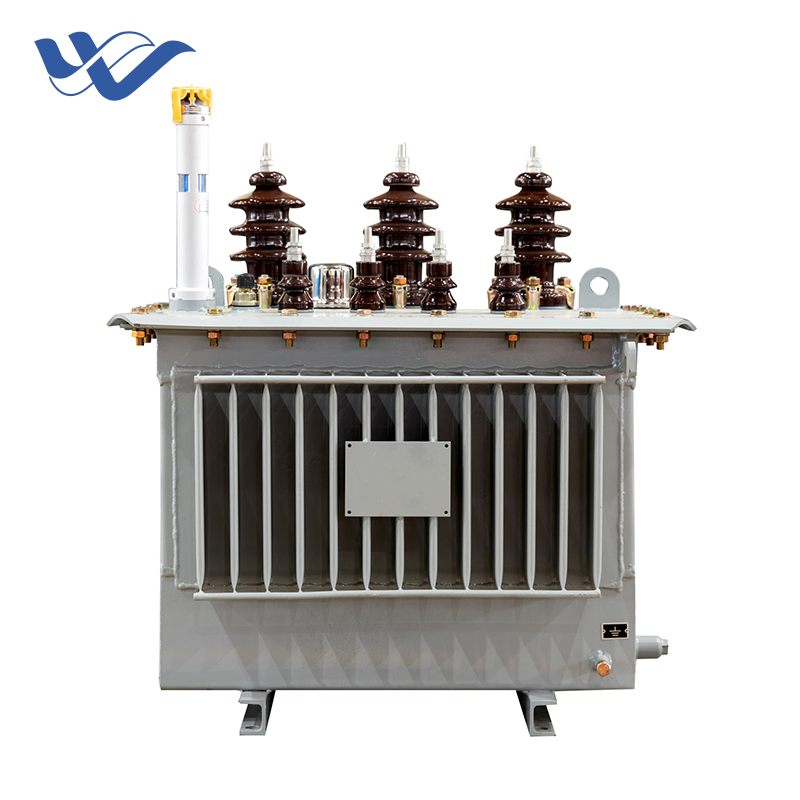
Natural convection is sufficient for smaller neighborhood units. Large-scale power distribution, however, requires engineered solutions to accelerate heat dissipation. The electrical industry uses standardized classifications to define these mechanisms. They dictate the maximum load capacity of the equipment.
This baseline method utilizes the natural convection cycle described earlier. It relies on ambient air breezes for cooling the external radiators. With no mechanical components, fans, or pumps, it is highly reliable and requires minimal long-term maintenance. It remains the standard for typical rural and suburban distribution networks.
Engineers employ the ONAF method when a facility needs to handle higher electrical loads without increasing its physical footprint. External industrial fans are mounted below or alongside the radiator banks. Internal sensors detect rising temperatures and activate these fans. They forcefully blow air across the fins. This rapid process strips heat away from the metal much faster than natural breezes. High-performance 35kV main transformers frequently utilize ONAN/ONAF configurations to support massive capacities up to 31500kVA safely during peak grid demands.
Natural convection is simply too slow to move heat away from the core for massive power assets. OFAF systems integrate heavy-duty mechanical pumps into the piping loop. These pumps actively draw hot fluid from the top of the tank, push it rapidly through the radiator banks, and force the chilled fluid back into the bottom. Combined with forced air fans, this system dramatically increases the thermal dissipation rate for heavy industrial facilities.
Simply pumping fluid through the main tank is insufficient in ultra-high-voltage applications. Inner winding layers can trap dangerous pockets of heat. ODAF systems solve this by using internal baffles and dedicated channels. Mechanical pumps force the cooled liquid directly into precise pathways within the winding structure itself. This ensures the most critical, heat-prone areas receive immediate, targeted thermal relief.
Global power grids are rapidly modernizing to accommodate decentralized renewable energy sources and the massive expansion of electric vehicle charging infrastructures. Consequently, the thermal demands on distribution assets have intensified significantly. Recent industry field data indicates a major shift toward digital, predictive thermal management. Utilities are increasingly retrofitting traditional units with industrial Internet of Things sensors. These smart devices provide real-time monitoring of top-oil temperatures and dissolved gases directly to control rooms. Operators can now shift from reactive maintenance to predictive thermal modeling. Furthermore, a growing regulatory push towards environmental compliance has sparked renewed interest in biodegradable ester fluids. While traditional oils dominate, hybrid cooling systems combining smart airflow controls with high-flash-point fluids are becoming the new standard for urban substations.
When evaluating electrical infrastructure for a new project, engineers must choose between dry-type and liquid-filled units. Dry-type designs have their place in indoor commercial buildings. However, liquid immersion is the undisputed standard for heavy-duty industrial applications.
Feature | Oil-Immersed Transformer | Dry-Type Transformer |
|---|---|---|
Cooling Efficiency | Exceptional liquid heat transfer | Limited by ambient air convection |
Voltage Capacity | Scalable to ultra-high voltages | Typically restricted to medium/low voltages |
Physical Footprint | Compact internal spacing due to high dielectric strength | Larger spacing required to prevent electrical arcing |
Outdoor Durability | Hermetically sealed steel tank withstands harsh weather | Vulnerable to moisture, dust, and chemical contaminants |
Air is a relatively poor conductor of heat. Electrical resistance generates continuous thermal energy, and air struggles to absorb and move this heat away fast enough. In contrast, insulating oil possesses a significantly higher heat capacity. It surrounds every microscopic crevice of the core and coil assembly, absorbing energy rapidly. Liquid thermal transfer is vastly more efficient. It becomes a mandatory engineering requirement for assets operating at or above 35kV to prevent catastrophic meltdown.
Another critical advantage is the drastic reduction in physical footprint. Because air is a weaker insulator, the internal components of a dry-type unit must be spaced relatively far apart to prevent electrical arcing. Liquid mediums provide exceptional isolation. Internal high-voltage components can be placed much closer together. Consequently, a liquid-filled asset can be designed with a significantly smaller core and tank size compared to a dry-type unit of the exact same power rating. This saves valuable real estate in crowded substations.
Power distribution networks must operate reliably in harsh, unpredictable conditions. This includes heavy rain, snow, and airborne chemical contaminants. Dry-type units typically feature louvered enclosures that expose internal coils to dust and moisture. Conversely, liquid-filled units are housed in hermetically sealed, heavy-gauge steel tanks. This robust exterior completely isolates the active internal components from the environment, making them the only logical choice for exposed outdoor installations.
A well-engineered system is only as effective as the fluid running through it. Over a standard 30-year operational lifespan, the liquid medium is subjected to continuous thermal stress, high electrical fields, and chemical oxidation. Proactive, scheduled maintenance is the absolute cornerstone of equipment longevity.
The first line of defense against breakdown is continuous monitoring. Industrial assets are equipped with an Oil Temperature Indicator and a Winding Temperature Indicator. Maintaining the correct fluid level in the conservator tank is equally critical. If the liquid level drops due to a microscopic leak or extreme winter contraction, the upper portions of the windings may become exposed to the air. Exposed windings lose both their thermal buffer and primary electrical insulation. This triggers an immediate failure.
As thermal and electrical stresses act upon the internal components, the fluid and cellulose paper slowly break down. They release microscopic trace gases. Dissolved Gas Analysis acts as an early warning system for internal faults. High levels of hydrogen often indicate partial electrical discharge. Elevated ethylene suggests severe, localized overheating. Routine testing of the fluid's breakdown voltage ensures it can still resist electrical stress without allowing a short circuit.
Moisture is the natural enemy of any high-voltage insulation system. Even trace amounts of water drastically reduce the insulating properties and accelerate paper decay. Most systems utilize silica gel breathers to strip moisture from incoming air as the fluid naturally expands and contracts. Prolonged heat exposure causes the fluid to oxidize over time. This forms a heavy, acidic sludge that coats components and traps heat. Technicians employ regular vacuum dehydration and chemical filtration to remove these contaminants.
Selecting the correct equipment requires a careful, highly technical analysis of load profiles, environmental conditions, and long-term operational goals. The specification is not a one-size-fits-all decision. It must be tailored precisely to the demands of the grid it will serve.
The foundational decision lies in selecting the appropriate classification. An ONAN system is typically sufficient and highly cost-effective for standard industrial applications with predictable loads. However, if a facility anticipates future expansion or experiences significant peak load fluctuations, an ONAF system is highly recommended. The integrated fans provide a crucial buffer for peak demand periods without requiring the purchase of a physically larger unit. Selecting a unit with a wide tapping range and low no-load loss ensures maximum operational efficiency.
Geographic location heavily influences the thermal design. Ambient temperature plays a critical role. A radiator can only shed heat if the surrounding air is cooler than the fluid inside. Standard radiators may struggle in regions with extreme summer temperatures, necessitating oversized banks. Altitude is another vital consideration. The thinner air at high elevations is less capable of absorbing heat. Engineers must apply specialized derating calculations to ensure the asset doesn't overheat under normal loads.
Ultimately, the efficiency and longevity of the asset depend heavily on original manufacturing quality. High-grade magnetic steel reduces core losses. Precision-welded, leak-proof tanks ensure the fluid remains uncontaminated. It is vital to source equipment from manufacturers who utilize premium components and highly refined mineral oil. This guarantees maximum thermal and electrical performance over decades of continuous service.
An oil immersed transformer stays cool through an elegant combination of fluid dynamics, high-quality liquid mediums, and engineered external radiators. This robust combination prevents dangerous overheating during heavy electrical loads and fluctuating grid demands. Proper maintenance, including moisture control and rigorous fluid testing, ensures grid stability, prevents costly downtime, and extends the equipment's lifespan significantly. Understanding these precise thermal mechanisms is essential for any facility manager or grid engineer. If you are planning a substation upgrade or new installation, contact our engineering team at HY Transformers for a detailed consultation. We will help you select the exact specifications and high-performance products to ensure absolute success for your next power distribution project.
Highly refined mineral oil remains the undisputed industry standard for the vast majority of power distribution applications. Its widespread adoption is due to its exceptional thermal conductivity, cost-effectiveness, and proven long-term stability under electrical stress. Synthetic esters and natural bio-based alternatives have gained traction for their higher flash points and biodegradability. Yet, traditional petroleum-based fluids offer the best balance of performance and economic value for standard utility use.
If the fluid exceeds its designed thermal limits, it initiates a destructive chain reaction. Excessive heat accelerates the chemical degradation of the cellulose paper wrapped around the copper windings, causing it to become brittle and weak. Simultaneously, the fluid oxidizes rapidly. This forms acidic sludge that blocks radiator channels and traps even more heat. Eventually, the compromised insulation will fail to contain the electrical current, leading to a catastrophic short circuit and asset failure.
Under typical load conditions, the top oil temperature usually operates between 50°C and 65°C. Industry standards generally allow a maximum top oil temperature rise of about 60°C above ambient temperature. If the ambient temperature is 40°C, the absolute maximum safe operating temperature for the fluid is around 100°C. Exceeding this threshold significantly accelerates insulation degradation.
For critical industrial substations and high-voltage transmission units, comprehensive fluid testing, including Dissolved Gas Analysis, should be conducted annually. Smaller distribution units might only require testing every three to five years. Frequent testing is the most reliable predictive maintenance strategy to detect microscopic faults before they escalate into major failures.
Yes, in many industrial scenarios, an ONAN unit can be retrofitted to function as an ONAF system. This is typically achieved by installing heavy-duty cooling fans directly onto or beneath the existing external radiators. Forcefully driving ambient air across the fins increases the rate of thermal dissipation dramatically. This retrofit can effectively boost the unit's safe load-handling capacity by up to 30%, provided automated temperature control panels are also installed to manage the fans.
The lifespan of the liquid medium is heavily dependent on operating conditions and proactive maintenance practices. Under normal load conditions and with a rigorous maintenance schedule, the fluid can easily last 20 to 30 years. This often mirrors the operational life of the asset itself. Achieving this longevity requires strict moisture control using silica gel breathers, routine diagnostic testing, and periodic vacuum dehydration to remove sludge and oxidation byproducts.


