

close
Choose Your Site
Global
Social Media
Views: 0 Author: Site Editor Publish Time: 2026-11-04 Origin: Site


Imagine walking onto the floor of a newly expanded manufacturing plant. Suddenly, you hear the agonizing hum of tripping breakers, followed by the costly silence of halted production lines. Are unexpected power bottlenecks threatening your output? Guessing industrial energy needs often triggers catastrophic equipment failures. On the flip side, heavily oversized units bleed precious capital and inflate standing energy losses. In this comprehensive guide, we strip away the guesswork. You will discover the precise engineering principles behind proper sizing. We will walk you through calculating the exact capacity required to build a resilient, efficient, and future-proof industrial facility.
Accurate Load Calculation is Crucial: You must systematically inventory the total connected load of all factory equipment, lighting, and climate control systems before selecting equipment. Guesswork inevitably leads to system instability.
Understand Real vs. Apparent Power: Factory loads are typically measured in kilowatts, representing real power. However, electrical infrastructure is sized by apparent power. Knowing your facility specific power factor is essential for this critical conversion.
Account for Inrush Currents: Heavy industrial motors require significantly more energy upon startup. Your electrical network must possess the dynamic capability to handle these temporary spikes without dropping voltage.
Plan for the Future: Always factor in a 20 percent to 25 percent safety margin for future expansions. This buffer prevents premature replacements when new automated production lines are added.
Select the Right Cooling Type: Choose between oil-immersed models and dry-type units based on your specific environmental conditions, load demands, and facility safety regulations.
Before diving into calculations, we must acknowledge how modern manufacturing is evolving. Recent industrial analyses reveal a rapid shift toward full electrification and smart automation. Factories are aggressively integrating heavy robotics, automated guided vehicles, and high-capacity electric vehicle fleet charging stations. Consequently, facility load profiles are becoming incredibly dynamic. Modern plant planning now demands transitioning from rigid sizing models to modular infrastructures capable of absorbing unpredictable energy spikes. A facility investor must view sizing through the lens of long-term return on investment, securing a stable foundation for the next two to three decades.
Picture the raw electrical power delivered by utility companies arriving at your facility edge. It pulses at voltages far too high for direct use by delicate CNC machinery or heavy stamping presses. Here, a robust Power Transformer acts as the critical intermediary. It safely steps down high-voltage utility power—often 10kV, 11kV, or 33kV—to a usable, standardized voltage like 400V or 480V required by the factory floor.
Once the voltage is stepped down, the energy moves from the grid interface via the internal electrical network. This intricate web includes main switchboards, sub-panels, circuit breakers, and heavy-duty cabling. The step-down unit functions as the beating heart of this entire system. If its capacity fails to align perfectly with the operational demands of the network, the entire manufacturing process is compromised. Proper sizing is not merely about finding a unit that turns on today. It is about engineering a stable, efficient foundation for continuous, round-the-clock industrial operation.
Selecting the incorrect capacity carries severe operational and financial penalties. Engineers must constantly balance capital expenditure against long-term operational reliability.
When the equipment lacks the capacity to handle the connected load, it operates in a continuous state of thermal stress. This leads to severe overheating, which rapidly degrades the internal cellulose insulation. Operationally, undersizing causes significant voltage drops during peak demand. You will likely experience frequent breaker tripping, erratic machinery behavior, and potential fire hazards due to thermal runaway. Thermal runaway is an engineer worst nightmare, often resulting in total equipment loss.
In contrast, heavily oversizing a unit represents a poor allocation of capital. Beyond the unnecessary upfront purchase and installation costs, an oversized unit incurs higher standing energy losses. Known within the industry as core losses, these energy drains occur continuously as long as the unit is energized. They happen regardless of the actual factory demand, resulting in poor long-term energy efficiency and inflated utility bills.
Determining the correct size begins with a meticulous physical audit of your facility power requirements. This hands-on process establishes the baseline Load Capacity that your infrastructure must reliably support.
To calculate the total connected draw, facility managers and electrical engineers must inventory every piece of equipment that consumes electricity. Walk the factory floor. Read the metal nameplates. This inventory should be strictly categorized to ensure no hidden power draws are overlooked.
Load Category | Typical Factory Equipment | Measurement Unit |
|---|---|---|
Heavy Machinery | CNC machines, lathes, stamping presses, extruders | Kilowatts or Horsepower |
Material Handling | Conveyor belts, industrial cranes, automated guided vehicles | Kilowatts or Horsepower |
Climate Control | Industrial chillers, ventilation fans, air compressors | Kilowatts |
Lighting | High-bay LED fixtures, exterior security lighting | Kilowatts or Watts |
Auxiliary and Office | Server rooms, computers, breakroom appliances | Kilowatts |
By summing the power requirements of these individual components, you establish the absolute maximum power the factory could draw if every switch were flipped simultaneously.
In reality, factories rarely operate every piece of equipment at full throttle at the exact same moment. To size the equipment safely and legally, engineers rely on strict guidelines. A continuous load is defined as any equipment expected to operate at maximum current for three hours or more. Primary HVAC chillers or continuous assembly line motors fall into this category.
According to standard engineering practices, you must size the unit to handle 100 percent of all continuous loads plus a specific multiplier for motor loads. Typically, calculations require adding 125 percent of the largest motor load to account for the disproportionate strain heavy machinery places on the system. This structured approach prevents dangerous undersizing while acknowledging realistic operational diversity.
A frequent point of confusion in industrial electrical design is the difference between real power and apparent power. While factory equipment loads are typically measured and listed in kilowatts, the main step-down units are universally sized, specified, and sold by their kVA Rating.
To bridge the gap between these two metrics, you must understand the power factor. In alternating current systems, the power factor is the ratio of real power used to perform actual, productive work to the apparent power that the utility grid must supply to the facility.
Industrial environments utilize many inductive loads, such as large electric motors, welding arrays, and high-intensity discharge lighting. Because of this, the voltage and current waveforms fall out of sync. This inefficiency means the facility draws more apparent power than it converts into useful mechanical work. In a typical heavy manufacturing plant, the power factor usually hovers between 0.8 and 0.9.
Converting your calculated load into a precise specification requires a straightforward mathematical formula. You simply divide the total kilowatts by the power factor.
To illustrate, suppose your comprehensive facility audit determines that the total continuous requirement for your factory is 800 kilowatts. If your facility electrical system has a known or estimated power factor of 0.8, the calculation is 800 divided by 0.8, which equals 1000 kVA. In this scenario, a 1000 kVA unit is the absolute minimum baseline required to supply the factory. Overlooking the power factor would lead to selecting an 800 kVA unit, resulting in immediate and dangerous undersizing.
Calculating the static running load is only half the engineering challenge. A robust industrial electrical design must account for the violent, dynamic startup phases of heavy equipment.
Large induction motors drive critical factory components like compressors, pumps, and heavy conveyors. These motors do not draw energy linearly. When an induction motor is first energized, it requires a massive surge of current to overcome mechanical inertia and establish a magnetic field. This initial shudder, known as inrush current, can draw five to seven times the standard full-load current for several seconds. If a factory relies on multiple large motors that start simultaneously or cycle frequently, the instantaneous demand skyrockets.
The electrical infrastructure must possess enough temporary thermal and magnetic capacity to absorb these severe spikes. If sized strictly for running loads without accounting for inrush currents, the sudden demand will cause a significant voltage sag across the entire network.
Voltage sags are highly disruptive in modern manufacturing. Even a temporary 10 percent drop in voltage can cause sensitive control electronics, like programmable logic controllers, to reboot. Variable frequency drives may fault out, and magnetic contactors can drop. This effectively shuts down production lines. Sizing to comfortably handle peak inrush currents ensures that voltage remains stable, protecting sensitive downstream equipment from electrical anomalies.
Industrial facilities are rarely static entities. As your business grows, so will your power needs. A facility investor must look ahead to maximize the return on investment over a typical operational lifespan of twenty to thirty years.
To prevent future operational bottlenecks, electrical engineers universally advise adding a safety buffer to your final calculations. The industry standard is to add a 20 percent to 25 percent spare capacity margin.
For example, if your calculated maximum load requires a 1000 kVA unit, you should specify a 1250 kVA model. This generous buffer allows the facility to seamlessly integrate future machinery additions, upgrade climate control systems, or increase production shifts without requiring a complete, highly disruptive, and expensive system overhaul.
When planning for massive future growth, facility managers must decide between purchasing one massive unit upfront or designing a modular Factory Supply network. While a single large unit may offer economies of scale regarding initial purchase price, a modular setup allows for parallel operation. Installing a moderately sized unit now, with switchgear designed to accept a second parallel unit later, spreads capital expenditure over time. Furthermore, it introduces vital redundancy. If one unit requires maintenance, the factory can continue operating at partial capacity rather than suffering a total blackout.
Once the electrical capacity is accurately calculated, the physical construction and cooling method must be selected. This decision relies heavily on the installation environment and specific application requirements. In industrial applications, facility engineers typically choose between two primary categories.
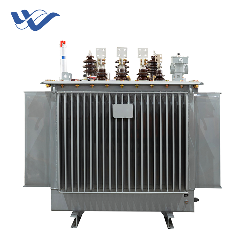
For the vast majority of heavy industrial applications, an oil-immersed unit remains the undisputed industry standard. These units utilize highly refined mineral oil as both a dielectric insulator and a cooling medium. The core and windings are completely submerged. This allows the fluid to absorb heat generated during operation and dissipate it through external radiators.
Specifically, a high-efficiency 10kV oil-immersed main unit typically features a capacity range from 30kVA up to 3150kVA. These units utilize high-permeability silicon steel cores to drastically reduce no-load losses. When specifying for a factory, engineers often select a Dyn11 or Yyn0 vector group to effectively manage harmonic distortion generated by variable frequency drives. Because of their robust construction and weather-resistant enclosures, they are perfectly suited for outdoor substations. By integrating external cooling fans, a facility can often increase continuous capacity by up to 25 percent, providing an excellent buffer for peak production cycles.
In contrast, dry-type units use ambient air or solid cast resin for cooling and insulation. This entirely eliminates flammable liquids. These are typically utilized indoors, specifically in environments where fire safety and environmental containment are strict regulatory concerns.
While safer for indoor installation, dry-type units generally have lower capacity limits. They are physically larger for the same rating and incur higher upfront costs. They also possess a lower tolerance for sustained overloads. Additionally, because they rely on ambient air, installing them in areas with heavy particulate matter requires expensive, highly filtered enclosures.
To assist in empirical decision-making, the following table outlines the primary operational differences between the two main types.
Specification Criteria | Oil-Immersed Models | Dry-Type Cast Resin Models |
|---|---|---|
Cooling Medium | Mineral Oil or Synthetic Esters | Ambient Air or Solid Resin |
Optimal Location | Outdoor Substations or Concrete Pads | Indoor Electrical Rooms |
Overload Tolerance | Excellent due to high thermal inertia | Limited due to rapid heat accumulation |
Maintenance Needs | Periodic oil sampling and leak checks | Visual inspections and periodic vacuuming |
Fire Hazard Risk | Moderate, requires containment firewalls | Extremely Low, self-extinguishing materials |
Capital Expenditure | Generally Lower | Generally Higher |
Procuring industrial electrical equipment is not an off-the-shelf transaction. To ensure the unit integrates flawlessly into your infrastructure, you must provide precise specifications to your manufacturer. Failing to define these parameters accurately can lead to equipment incompatibility or severe safety hazards.
The foundational specifications dictate how the equipment interfaces with both the utility grid and your internal Distribution network. You must specify the exact primary voltage provided by your utility company, such as 10kV or 11kV. You also need the specific secondary voltage required by your factory floor, such as 415V or 480V. Industrial facilities almost exclusively require three-phase power, but this must be explicitly stated. Furthermore, ensure the unit matches your regional grid frequency, typically 50Hz in Europe and Asia, or 60Hz in North America.
Specifying the correct percentage impedance is vital. Impedance dictates how much short-circuit current will flow through the system in the event of a catastrophic fault. The impedance must be carefully coordinated with the interrupting capacity of the factory main circuit breakers. If the impedance is too low, a short circuit could overwhelm the breakers, leading to severe damage. Conversely, a higher impedance limits fault currents but results in worse voltage sags during motor startups. For a typical 1000 kVA to 2000 kVA unit, an impedance of 5 percent to 6 percent offers an optimal engineering balance.
To maximize the lifespan of your investment, the unit should be equipped with standard protective relays and monitoring devices. Essential accessories include a Buchholz Relay for detecting internal gas accumulation, a Silica Gel Breather to prevent moisture ingress, and Winding Temperature Indicators. These sensors provide real-time thermal data. They should be wired to your facility control system to automatically trigger cooling fans or shed non-essential loads if thermal limits are approached.
Determining the correct size for your facility electrical infrastructure requires careful auditing and precise calculations. You must inventory your total electrical load accurately, factor in the specific power factor of your facility, and account for the violent startup currents of heavy industrial motors. By adding a generous 20 percent buffer, you ensure smooth future expansions without facing crippling power bottlenecks.
Before finalizing any purchase or installation plan, we strongly advise consulting with a licensed electrical engineer to verify all empirical calculations. Ready to secure a reliable power foundation for your manufacturing plant? Visit HY Transformers to explore our complete catalog. Whether you need a standard 10kV oil-immersed unit or a custom-engineered dry-type solution, our technical team will help you match the exact specifications to your facility demands, ensuring maximum efficiency and long-lasting performance.
Calculating the required capacity for a three-phase system differs from standard single-phase calculations due to the phase geometry. The empirical formula used by electrical engineers is: Volts multiplied by Amps multiplied by 1.732, all divided by 1000. In this formula, Volts refers to the line-to-line voltage, Amps is the total maximum current draw of your facility, and 1.732 is the square root of 3. For example, if your factory requires a maximum of 1200 Amps at 480 Volts, the calculation yields approximately 997 kVA. In this scenario, you would round up to the next standard commercial size, which is typically a 1000 kVA or 1250 kVA unit.
Operating a facility on an undersized unit is highly inadvisable and poses severe operational risks. When subjected to loads exceeding its nameplate rating, internal temperatures rise exponentially. According to thermal degradation laws applied to electrical insulation, every ten-degree Celsius rise above the rated operating temperature effectively halves the lifespan of the cellulose paper insulation. Temporarily overloading the unit will cause the insulating oil to degrade rapidly, producing combustible gases. This not only risks immediate tripping of protective relays but also creates a severe risk of internal arcing, catastrophic fire, and permanent destruction of the equipment.
In an industrial environment, a power factor ranging between 0.85 and 0.95 is generally considered acceptable and efficient. The power factor is the ratio of real power, which performs actual work, to apparent power, which is the total power drawn from the grid. Heavy induction motors, CNC machines, and welding equipment introduce reactive power into the system, dragging the power factor down. A low power factor means your infrastructure must draw significantly more apparent power to deliver the required real power. Facilities can optimize this by installing capacitor banks at the main switchgear to neutralize reactive power, thereby optimizing efficiency and avoiding utility penalty fees.
A well-maintained, properly specified oil-immersed unit is one of the most durable pieces of equipment in a factory setting. It can easily remain operational for twenty-five to thirty years. However, this longevity is strictly contingent upon rigorous maintenance protocols. The primary cause of premature failure is the degradation of the insulating oil and paper due to moisture ingress or chronic overheating. Facility managers must conduct annual dissolved gas analysis tests on the oil. With strict adherence to load limits and regular oil filtration, these robust units can sometimes exceed forty years of continuous service.
The choice between a single large unit and multiple smaller units depends entirely on your facility operational tolerance for downtime and the physical layout of the plant. Purchasing one massive unit is generally more cost-effective in terms of upfront capital expenditure. However, it creates a single point of failure. If that unit requires maintenance, the entire factory loses power. Utilizing multiple smaller units offers robust redundancy. If one unit fails, critical loads can often be re-routed through tie-breakers to the remaining operational units. Placing smaller units closer to the actual machinery also reduces the length of low-voltage cable runs, significantly decreasing energy losses across the factory floor.
The choice between copper and aluminum windings comes down to upfront cost versus long-term footprint and efficiency. Copper is a superior electrical conductor. It allows manufacturers to build a smaller, more compact unit with excellent short-circuit resistance and lower overall energy losses. However, copper units carry a premium price tag. Aluminum wound units are more cost-effective upfront but are physically larger to achieve the same conductivity and capacity. For heavy industrial applications where space is limited and continuous, high-efficiency operation is critical, engineers generally recommend copper windings despite the higher initial investment.
Lead times can vary significantly based on global supply chain conditions, material availability, and the complexity of your specifications. For standard distribution units, lead times generally range from eight to twelve weeks. However, if your factory requires a highly customized unit with specific impedance ratings, specialized cooling configurations, or unique footprint constraints, the engineering and manufacturing process can extend from sixteen to twenty-four weeks. It is crucial to engage with a manufacturer like HY Transformers early in your facility planning stage to ensure the equipment arrives exactly when your construction schedule demands.


